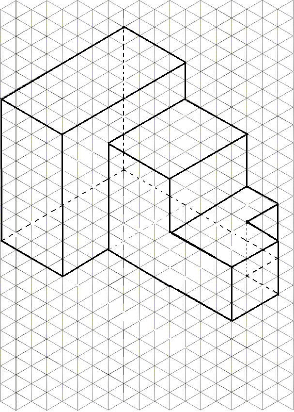
Perspective grid also known as perspective paper or point perspective grid drawing paper helps artists create drawings with depth. Click any paper to see a larger version and download it. Provides cost effective and high quality services from india.
3d drawings on isometric paper

Eileen shirley 813 832 4247 land line 813 373 9500 cell 4604 w.
3d drawings on isometric paper. Program for piping isometric drawings. The following video shows how to make an isometric cubes drawing when provided with a front view a side view and a top view. Perspective grid in pdf format. More than merely the drawing of pictures it is also a languagea graphical language that communicates ideas and information from one mind to another.
Cypecad was brought about to carry out the analysis and design of reinforced concrete and steel structures subject to horizontal and vertical forces for houses buildings and civil work projects. Engineering drawing the activity produces engineering drawings the documents. 4 programs of openpipe are such customized programs. Download these free pdf files and print your own isometric graph paper also known as 3d drawing paper you can use these files for free and print as many sheets as you want.
Reliable structures very precise drawings. The iso program is totally based on lisp programs and there are only 4 small symbols or blocks to be inserted as in other programs due to which there is a lot of saving of disk space as well as the drawing also has. As with all types of parallel projection objects drawn with isometric projection do not appear larger or smaller as they extend closer to or away from the viewerwhile advantageous for architectural drawings where measurements need to be taken directly the result is a perceived distortion as unlike perspective projection it is not how human vision or photography normally work. 3d labs familiar in mechanical and thermal and process design for pressure vessel and heat exchanger and storage tanks.
An engineering drawing a type of technical drawing is used to fully and clearly define requirements for engineered items. Most cad packages are prepared in such a manner that these can be easily customized.


